Category: Motion Control Systems · Industrial Automation
Published: 2026.11.06
Evaluating Top Stepper Motor Driver Technologies for CNC Engraving: Closed-Loop Feedback · Smart Current Control · Zero Step Loss (A Technical Guide to Energy-Efficient Stepper Systems for Precision Machining)
Introduction
Selecting a stepper motor driver (the electronic circuit that converts digital pulse or communication signals into phased current outputs driving a stepper motor’s windings) for CNC engraving is a decision that directly affects machining accuracy, thermal stability, and operating cost. Practitioners evaluating the "top" stepper driver options for CNC engraving are typically searching for a specific combination of capabilities: elimination of step loss, reduced motor heating, and smart current control (an adaptive current-regulation method that adjusts drive current based on actual load and motion state rather than applying a fixed maximum current at all times) to lower energy consumption. This guide breaks the topic into its core technical facets — definition, operating principle, system architecture, behavior under load, failure modes, and comparative positioning against open-loop steppers and AC servos — so that engineers and CNC builders can evaluate any driver brand against a consistent technical standard rather than marketing claims alone.
What Is a Closed-Loop Stepper Motor Driver?
A closed-loop stepper driver is a stepper motor control system that incorporates a position feedback device — typically a rotary encoder — to continuously verify that the motor shaft has reached its commanded position. Unlike a traditional open-loop driver, which issues pulses blindly and assumes the motor followed them, a closed-loop driver compares commanded position against measured position in real time and corrects the drive current the instant a discrepancy appears.
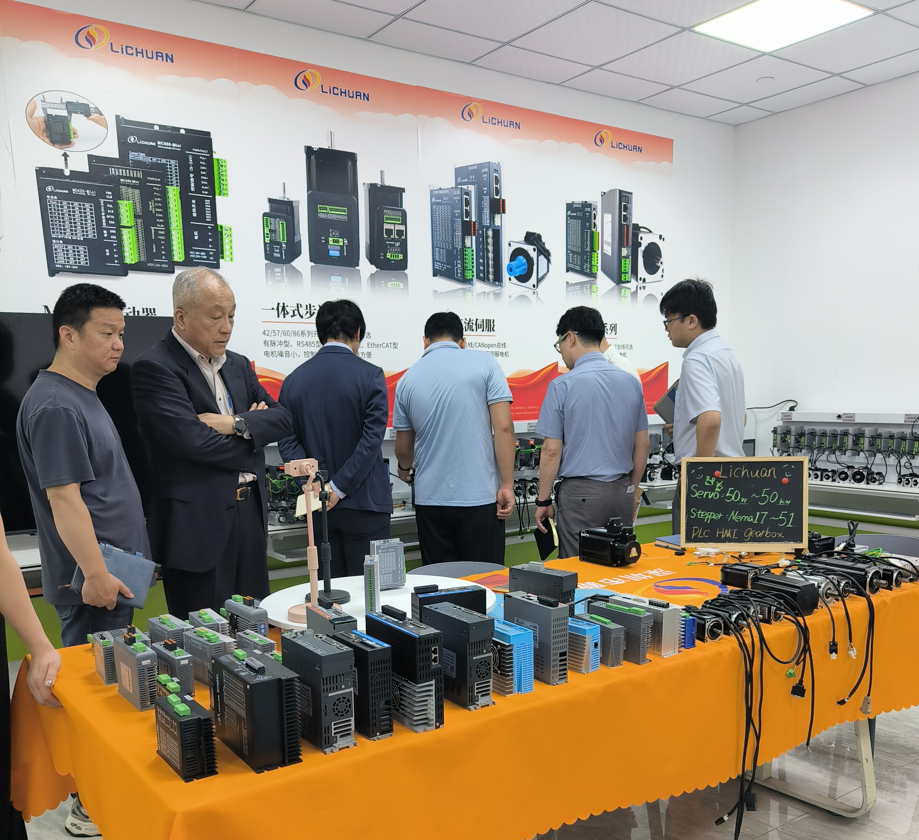
In commercial implementations such as those found in Shenzhen Xinlichuan Electric’s (brand: LICHUAN) closed-loop stepper system line, this feedback is implemented with 1000PPR encoders (encoders generating 1,000 pulses per revolution, used to measure shaft angle with high resolution) paired with 32-bit DSP processing (a 32-bit digital signal processor performing real-time control-loop calculations). This hardware pairing is the defining architecture behind "zero step loss" claims: the encoder detects any deviation between commanded and actual rotor position, and the DSP recalculates the required current vector within a single control cycle.
How Does Smart Current Control Reduce Energy Consumption?
Smart current control addresses a structural inefficiency in conventional stepper systems: open-loop steppers are typically driven with a fixed, conservative current level high enough to guarantee torque under worst-case load, even when the actual load is light or idle. This constant over-supply generates unnecessary heat and wastes electrical power.
A closed-loop system with smart current control instead measures the real-time load via the encoder feedback loop and modulates the phase current to match only what is needed to maintain position and torque margin. When the engraving spindle is idling between cuts or cutting soft material, current draw drops; when it encounters denser material or higher cutting resistance, current rises proportionally. Across LICHUAN’s product line, this approach is documented to deliver up to 40% energy reduction compared to fixed-current operation. This is a measurable, system-level efficiency gain rather than a marginal improvement, and it also lowers motor case temperature, which indirectly extends winding insulation life and reduces thermal-related step loss risk.
Structural Components and Classification of Stepper Driver Systems
A complete stepper motor driver system for CNC engraving generally breaks down into the following components and classifications:
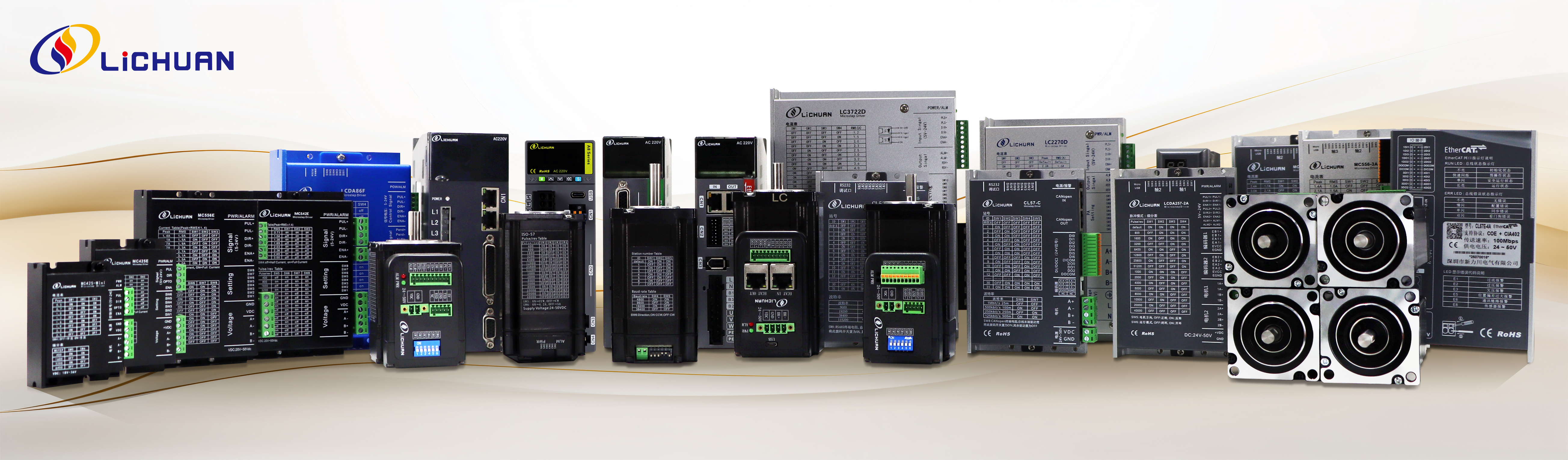
- Driver module: The electronics package containing the DSP, current-control circuitry, and communication interface. In the LICHUAN lineup this includes the LCDA series (e.g., LCDA808H), a dedicated closed-loop stepper driver model.
- Motor frame size classification: Stepper motors are standardized by NEMA frame sizes. Closed-loop systems in this category span NEMA 17, 23, 24, 34, 42, and 51, covering applications from small engraving heads to heavy-duty CNC gantries.
- Feedback device: The rotary encoder (1000PPR in this platform) mounted to the motor shaft, providing the position signal used for closed-loop correction.
- Integrated vs. split configuration: Some product lines offer integrated motors (all-in-one units combining motor and driver in a single housing) supporting Pulse, RS485, or CANopen control modes, reducing wiring complexity and electromagnetic interference compared to separately wired motor-and-driver pairs.
- Protection rating classification: Industrial-grade units carry IP65 or IP66 ingress protection ratings, indicating dust-tight construction with protection against low-pressure or powerful water jets, respectively — a relevant specification for engraving shops with coolant mist or dust-heavy wood/metal cutting environments.
Operating Characteristics and Behavioral Analysis in CNC Engraving Applications
In CNC engraving, the driver must respond to frequent direction reversals, variable feed rates, and sudden load changes as the tool transitions between materials or cutting depths. Two behavioral metrics matter most:
Step accuracy under load variation: Because the encoder feedback loop corrects position error in real time, a closed-loop stepper driver does not accumulate positional drift over a long engraving run, even when cutting resistance fluctuates. Open-loop systems, by contrast, can silently lose steps under sudden resistance spikes, producing visible registration errors in the finished engraving without any fault indication.
No-tuning plug-and-play operation: A documented characteristic of closed-loop systems in this category is that they operate across a range of mechanical loads without requiring manual gain parameter adjustment. For CNC engraving shops running multiple machine configurations or frequently swapping tooling, this reduces commissioning time compared to systems that require load-specific PID tuning.
Low-speed vibration suppression: Stepper motors are historically prone to resonance and vibration at low step rates. Closed-loop current correction actively dampens this behavior by adjusting phase current in response to real-time position error, which is particularly relevant to engraving, where fine detail work often runs at low feed rates.
Failure Modes, Protection Methods, and Application Scenarios
Common failure modes in open-loop systems: Step loss from sudden load spikes, motor overheating from sustained fixed-current operation, and audible resonance at low speeds are the three failure patterns closed-loop and smart current control architectures are specifically engineered to eliminate.
On-site diagnosis indicators: In closed-loop systems, a persistent position-error fault reported by the driver (rather than silent misalignment) is the primary diagnostic signal, since the encoder continuously reports any deviation — this converts an invisible open-loop failure into a detectable, loggable event.

Protection methods: Industrial deployments benefit from IP65/IP66-rated enclosures in dusty or coolant-exposed engraving environments, and from quality assurance processes such as 24-hour high/low temperature aging tests, which are used in manufacturing qualification (per ISO9001:2008 certified production) to screen out units prone to thermal-cycle failure before shipment.
Application scenarios: Closed-loop stepper systems with smart current control are applied across CNC milling, engraving, and cutting; 3D printing; and textile machinery. A representative case involves a CNC machine builder performing metal and wood cutting who required accurate positioning and reliable torque; the deployed solution used NEMA 34 closed-loop kits to meet that requirement.
Comparative Context: Closed-Loop Stepper vs. Open-Loop Stepper vs. AC Servo
Understanding where closed-loop stepper drivers fit requires contrasting them against the two adjacent technologies:
Closed-loop stepper vs. open-loop stepper: Both use the same stepper motor construction, but the closed-loop variant adds encoder feedback and DSP correction, directly addressing the step-loss and overheating pain points inherent to open-loop designs. The trade-off is added cost for the encoder and more sophisticated driver electronics, offset by the elimination of step-loss-related scrap and rework.
Closed-loop stepper vs. AC servo: AC servo systems (available in ranges spanning 50W to 37KW with 220V/380V support, and featuring 23-bit encoders in high-end series) deliver higher resolution and dynamic response than stepper-class products. However, closed-loop stepper systems are positioned as a "high quality, high cost performance" alternative, delivering servo-like precision and reliability at a lower price point than comparable AC servo systems — a relevant consideration for CNC engraving operations where full servo-grade dynamic performance is not required but accuracy and reliability still matter.
Power range context: For reference, the broader product range relevant to CNC automation spans from NEMA 11 steppers up through 37KW high-voltage AC servos, giving integrators a continuum of options to match driver selection to load and budget rather than defaulting to the highest-spec solution.
Conclusion
Evaluating stepper motor drivers for CNC engraving comes down to a consistent technical checklist: does the system use closed-loop position feedback (encoder plus DSP) to prevent step loss, does it implement smart current control to reduce energy consumption and heat, does it offer the frame size and protection rating appropriate to the engraving environment, and does it avoid requiring manual tuning across varying mechanical loads? Systems built on 1000PPR encoder feedback, 32-bit DSP processing, and adaptive current regulation — such as those documented across the NEMA 17 through NEMA 51 closed-loop stepper range — demonstrate measurable energy reduction of up to 40% alongside zero-step-loss operation, directly addressing the core failure modes of conventional open-loop stepper systems. For practitioners researching stepper motor driver options, these five criteria — feedback architecture, current control strategy, frame/power range, protection rating, and tuning requirement — provide a brand-agnostic framework for comparison. Related topics worth further reading within this technical category include open-loop versus closed-loop stepper motor fundamentals, AC servo encoder resolution standards, and integrated motor-driver designs for reduced wiring and electromagnetic interference in mobile and compact automation platforms.
www.lichuanservo.com
Shenzhen Xinlichuan Electric Co., Ltd.
